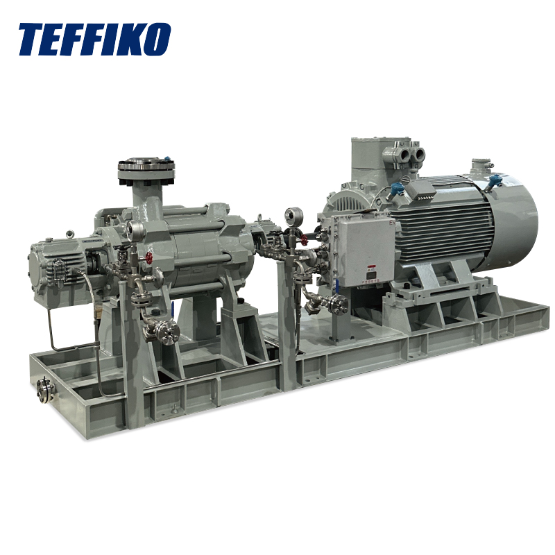
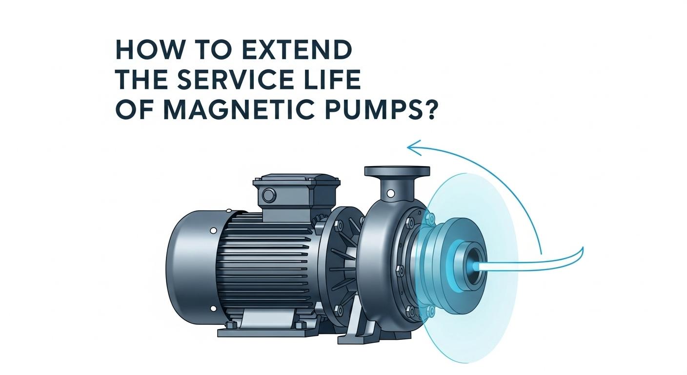
As a core fluid handling equipment in industry, centrifugal pumps operate through sophisticated energy conversion principles. This article analyzes key processes including priming, impeller energy transfer, and volute pressure conversion to help readers master equipment selection and operational maintenance.
1. Startup Preparation Stage - Laying the Foundation for Operation
Before starting the centrifugal pump, the priming operation is an essential and crucial step. Since the centrifugal pump itself does not have self-priming ability, if there is air in the pump body and the suction pipeline, the density of air is much lower than that of the liquid. The centrifugal force generated by the rotation of the impeller is not sufficient to effectively discharge the air, so it is impossible to create a sufficient low-pressure area at the center of the impeller, and the liquid cannot be sucked into the pump.
There are usually two methods for priming. One is the high-level water tank priming, that is, the liquid in the high-level water tank is used to fill the pump body and the suction pipeline by gravity flow. The other is the vacuum pump priming, in which the vacuum pump is used to extract the air from the pump body and the suction pipeline, allowing the liquid to enter the pump under the action of atmospheric pressure. No matter which priming method is adopted, it is necessary to ensure that all the air in the pump body and the suction pipeline is completely exhausted to ensure the normal startup of the centrifugal pump.
2. Energy Conversion Stage - Core Power Output
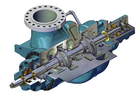
When the motor is powered on and started, it drives the impeller to rotate at a very high speed, usually between 1450 - 2900 rpm. The liquid between the impeller blades, under the action of the centrifugal force, is thrown outward as if by an invisible big hand, rapidly moving from the center of the impeller to the outer edge of the impeller.
During this process, the motion state of the liquid changes significantly, and its speed increases greatly, thus obtaining higher kinetic energy. At the same time, as the liquid is quickly thrown to the outer edge of the impeller, the mass of the liquid at the center of the impeller decreases, forming a low-pressure area. According to the law of conservation of energy, the mechanical energy input by the motor is converted into the kinetic energy and pressure energy of the liquid through the rotation of the impeller. The increase in kinetic energy is mainly reflected in the increase of the liquid flow velocity, while the increase in pressure energy is manifested as the pressure difference between the low-pressure area at the center of the impeller and the high-pressure area at the outer edge of the impeller.
3. Liquid Transportation Stage - Conversion and Output of Pressure Energy
After the high-speed liquid is thrown out from the outer edge of the impeller, it immediately enters the pump casing. The gradually expanding flow passage of the pump casing causes the flow velocity of the liquid to gradually decrease. According to Bernoulli's equation, as the flow velocity decreases, the pressure energy of the liquid increases accordingly. In this process, the kinetic energy of the liquid is gradually converted into pressure energy, and finally, the liquid is discharged from the pump outlet at a relatively high pressure, achieving the effective transportation of the liquid.
In order to improve the energy conversion efficiency of the liquid in the pump casing, the design of the pump casing needs to precisely consider factors such as the expansion angle, length, and surface roughness of the flow passage. A reasonable design can make the flow of the liquid in the pump casing smoother, reduce energy loss, and improve the head and efficiency of the pump.
4. Continuous Circulation Process - Maintaining Stable Transportation
As the impeller continuously throws out the liquid, the center of the impeller always remains in a low-pressure state. Under the action of the pressure difference between the external atmospheric pressure or other pressure sources (such as the static pressure of the high-level liquid) and the low-pressure area at the center of the impeller, the liquid in the suction pipeline is continuously sucked into the center of the impeller to fill the space left by the thrown-out liquid.
In this way, the centrifugal pump forms a continuous liquid transportation circulation process. As long as the motor continues to operate and the impeller maintains high-speed rotation, the liquid can continuously enter the pump from the suction pipeline, and after energy conversion, it is discharged from the outlet, providing stable liquid transportation services for various industrial production and daily life applications.
We use cookies to offer you a better browsing experience, analyze site traffic and personalize content. By using this site, you agree to our use of cookies.
Privacy Policy