Athena Engineering S.r.l.
News

Detailed Explanation of Common Flushing Plans 1/11/53A/53B

2025-11-26

In the installation, commissioning, maintenance and upkeep of industrial fluid systems (such as pumps, valves, pipelines, heat exchangers and other equipment), the flushing plan is a core process to remove impurities (weld slag, rust, dust, oil stains) in the system and ensure the safe operation of equipment. This article focuses on the most commonly used plans in the industrial field: Plan 1, Plan 11, Plan 53A, and Plan 53B, and elaborates on them from dimensions such as applicable scenarios, core principles, operation procedures, key parameters, and precautions, balancing technical professionalism and practical guidance to meet the application needs of pumps, valves, seals and other equipment.

I. Plan 1: Single-Loop Straight-Through Flushing (Basic Universal Type)

1. Core Definition

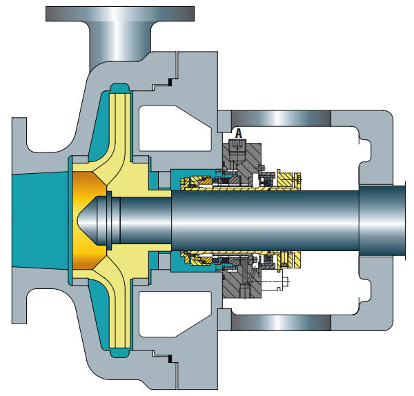
Plan 1 does not require any external pipelines.It serves as the internal flushing pipeline for mechanical seals.Unlike Plan 11, the flushing pipeline is not exposed to the atmosphere, thus preventing high-viscosity fluids from freezing/polymerizing at low temperatures.

Seal chamber details

2. Applicable Scenarios


  • Usually used for horizontal pumps.
  • High-viscosity liquids that are prone to thickening, solidification or polymerization.
  • More suitable for ANSI pumps.


3. Precautions


  • The flow rate of the flushing fluid must be sufficient to remove heat from the mechanical seal chamber.
  • Unlike Plan 11, the flushing fluid is rarely directed to the seal face.
  • Not recommended for dirty products, as they can easily clog the flushing pipeline.
  • Not applicable to vertical pumps.


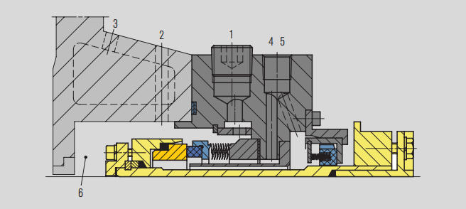
Seal Chamber Details


  1. Flushing port (F), plugged (for possible future circulating fluid or venting of vertical pumps)Seal Chamber Details
  2. Vent port (V), if required
  3. Heating/cooling inlet (HI or CI), heating/cooling outlet (HO or CO), if required
  4. Cooling water flow rate (Q)
  5. Drain port (D)
  6. Seal chamber


II. Plan 11: Circulating Filtration Flushing (Enhanced Cleaning Type)

1. Core Definition


  • Default flushing plan for all single seals.
  • Serves as the flushing and self-venting plan for horizontal pumps.
  • Helps create additional vapor pressure margin in the seal chamber.
  • Uses flow control orifices to limit the flow of flushing fluid to the mechanical seal.
  • Uses distributed flushing to make cooling and lubrication more effective.


2. Applicable Scenarios


  • Generally suitable for all general purposes, except when the pressure difference between the pump discharge port and the seal chamber pressure is small.


3. Precautions


  • For high-head applications, the orifice size and/or number of orifices must be calculated very carefully. The minimum orifice size should be 3 millimeters (1/8").
  • The throat bushing clearance and orifice size together ensure that the flushing fluid can flow correctly to the seal.
  • Always check the difference between the discharge port and the seal chamber pressure. If the difference is too low, Plan 13 should be preferred.
  • Media containing solids, abrasives or easily polymerizable substances should be avoided.
  • The clogging of the orifice plate can be confirmed by checking the surface temperature of the pipeline upstream and downstream of the orifice plate.


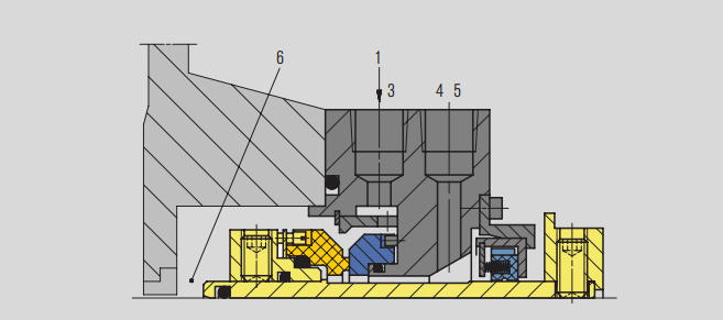
Seal Chamber Details

Seal Chamber Details

1.From the high-pressure area of the pump (pump discharge or pump discharge pipeline)
3.Flushing port (F)
4.Cooler (Q)
5.Drain port (D)
6.Seal chamber


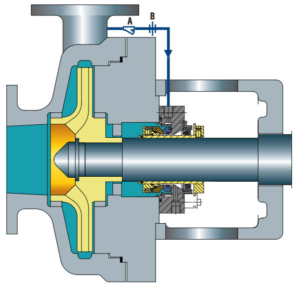
Seal chamber details


                                  A Strainer                    B Fow control orifice


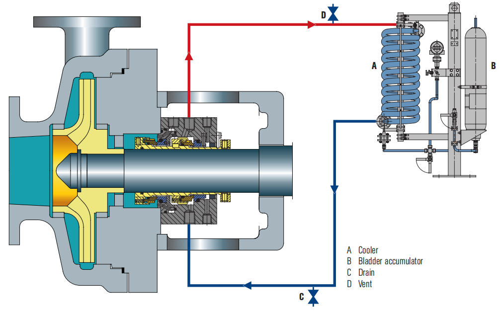
III. Plan 53A: Dual-Loop Parallel Flushing (Efficient Split-Flow Type)

1. Core Definition


  • The pumped medium will not leak to the atmosphere unless the tank pressure is lost.
  • Pressurization requires a nitrogen source.
  • Provides cooling coils inside or outside the tank to remove heat.
  • Uses an internal circulation device to ensure the circulation of the barrier fluid.
  • The barrier fluid enters the process medium through the inner seal face.


2. Applicable Scenarios


  • Suitable for working conditions where the product medium is allowed to be diluted.
  • Suitable for working conditions where the medium cannot provide lubrication for the inner seal face.
  • Suitable for scenarios where the isolation pressure is up to 16 bar (232 psi).


3. Precautions


  • Ensure that the source pressure is higher than the required isolation pressure.
  • Vent the system before starting the equipment. Subsequently, ensure that the vent pipeline is always kept closed.
  • Monitor the temperature of the inlet and outlet pipelines of the seal. A temperature difference indicates that the flushing flow rate is in a normal state.
  • A drop in the liquid level of the storage tank indicates leakage of the inner and/or outer seals.
  • Ensure that the isolation pressure is always at least 1.4 bar (20 psi) higher than the seal chamber pressure.
  • If the isolation pressure is higher than 16 bar (232 psi), Plan 53B, 53C or 54 should be adopted.
  • Confirm with the process engineer whether the product medium is allowed to be contaminated.
  • Ensure the compatibility between the isolation fluid and the medium pumped by the pump.


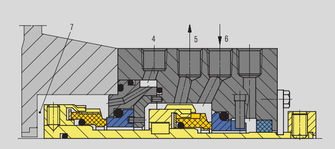
Seal Chamber Details

4.Flushing (F)

5.Liquid barrier outlet (LBO)

6.Liquid barrier inlet (LBI)

7.Seal chamber


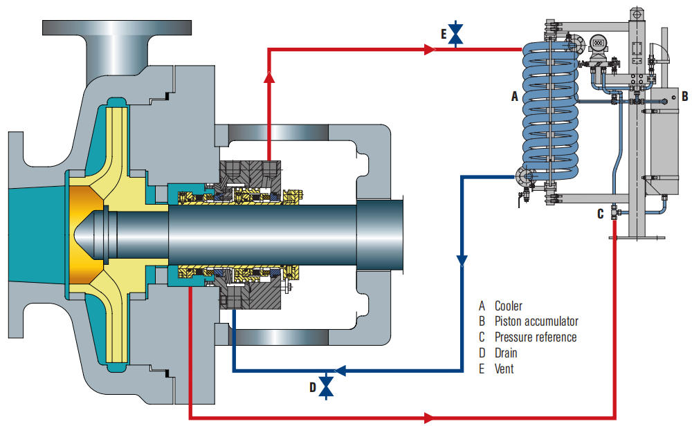
IV. Plan 53B: Dual-Loop Series Flushing (Deep Cleaning Type)

1. Core Definition


  • The barrier fluid and nitrogen are separated by a diaphragm, which can effectively prevent the mixing of nitrogen and the barrier fluid, similar to Plan 53A.
  • The pumped medium usually will not leak to the atmosphere unless the bladder pressure is lost.
  • As an independent system, it has high reliability and does not require a permanent nitrogen source and external pressure.
  • Heat recovery is performed through a water or air cooler. An internal circulation device is used to ensure the circulation of the barrier fluid.
  • The barrier fluid enters the process medium through the inner seal face.


2. Applicable Scenarios


  • Suitable for working conditions where the product medium is allowed to be diluted.
  • Suitable for working conditions where the medium cannot flush the inner seal face.
  • Suitable for working conditions where Plan 53A cannot be adopted due to the inability to obtain a continuous and stable nitrogen source at the required pressure.
  • Suitable for application scenarios where the isolation pressure is higher than 16 bar (232 psi) and Plan 53A cannot be adopted.


3. Precautions


  • Confirm with the process engineer whether the product medium is allowed to be contaminated.
  • Verify the compatibility between the isolation fluid and the pumped medium.
  • Ensure that the bladder diaphragm is pre-charged at the correct pressure to achieve the required isolation pressure at the operating temperature. Please refer to the nameplate attached to the accumulator.
  • Vent the system before starting the equipment. Subsequently, ensure that the vent pipeline is always kept closed.
  • Monitor the temperature of the inlet and outlet pipelines of the seal. A temperature difference indicates that the flushing flow rate is in a normal state.
  • Ensure that the isolation pressure is always at least 1.4 bar (20 psi) higher than the seal chamber pressure.
  • Due to the small capacity of the isolation fluid in the accumulator, the heat dissipation effect depends on the efficiency of the cooler.


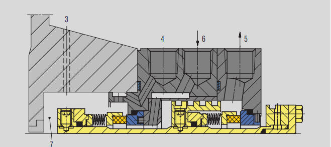
Seal Chamber Details

3.Pressure reference point

4.Flushing (F)

5.Liquid barrier output (LBO)

6.Liquid barrier input (LBI)

7.Seal chamber


Seal chamber details


Conclusion

If you want to learn more professional knowledge about industrial fluid system flushing plans, pump and valve maintenance, or customized solutions for fluid equipment, please visit our official website www.teffiko.com. For technical consultation or business cooperation, you can also contact us via email at sales@teffiko.com. We are committed to providing you with high-quality technical support and practical industry insights.


Related News
X
We use cookies to offer you a better browsing experience, analyze site traffic and personalize content. By using this site, you agree to our use of cookies. Privacy Policy
Reject Accept