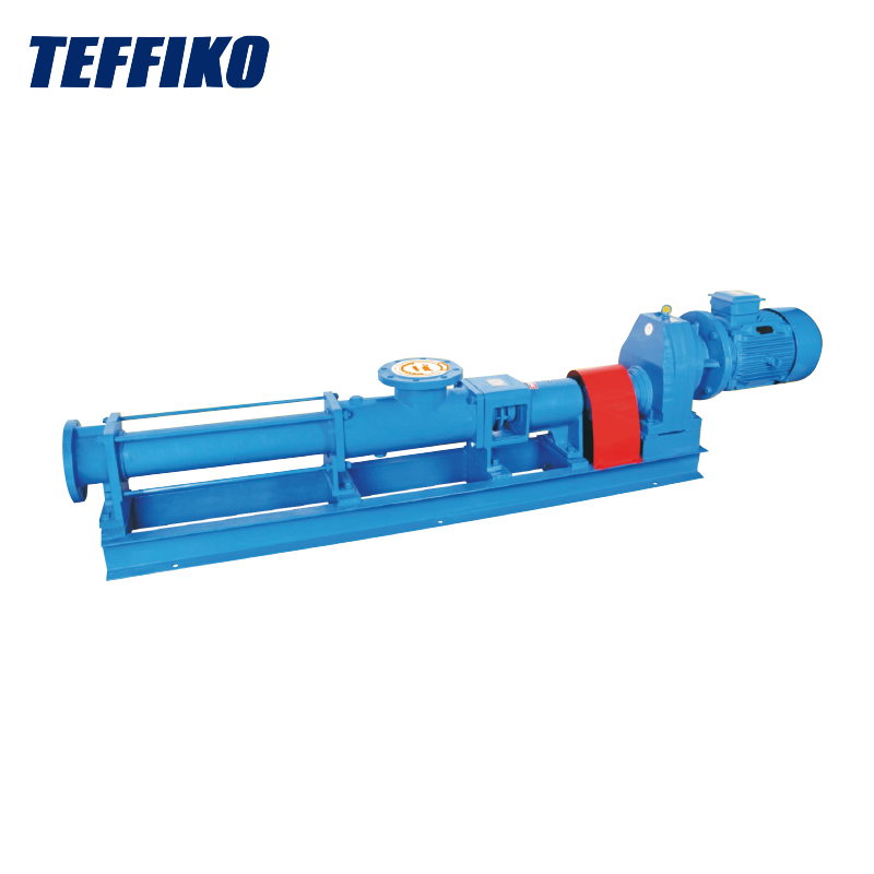
Teffiko recognizes that chemical pumps are equipment with high energy consumption in chemical production. Many factory pumps operate far from the best‑efficiency point for long periods, with flow regulated by valve throttling, resulting in substantial waste of electric energy. The losses of chemical pumps mainly fall into three categories: hydraulic loss, volumetric loss and pipeline leakage loss. Energy‑saving retrofitting requires systematic implementation covering selection, maintenance, components, speed regulation, pipelines, operation and maintenance, so as to achieve stable energy consumption reduction and mitigate faults such as cavitation and seal failure.
I. Original‑Source Selection
Excessive selection margin is the root cause of high energy consumption for most chemical pumps. For many projects, pumps are selected with an additional 20%‑30% margin based on maximum working conditions. In actual operation, pumps run in the low‑flow zone for long periods, deviating far from the high‑efficiency point.
Recheck working‑condition curves: Plot the system resistance curve according to actual medium density, temperature, flow rate and head, and check the pump operating position against the pump performance curve. For acid‑base, slurry and high‑viscosity media, actual working conditions will change; clean‑water parameters shall not be applied mechanically.
Optimize pump unit configuration: For scenarios with large flow fluctuations, adopt large‑and‑small pump combinations and automatic switching of multiple parallel pumps for start‑stop on demand, so that each pump operates close to its high‑efficiency zone.
II. Optimize Maintenance Procedures
Hydraulic loss refers to energy loss caused by flow‑path friction, vortex and impact. Standardized maintenance and polishing represent a low‑input, quick‑effect energy‑saving measure.
Improve flow‑path surface finish: Polish rust, scale and burrs on key parts including impeller inlets, outlets and positive guide vanes to achieve a surface roughness of Ra 4 or above with metallic luster exposed. Do not alter the original profile of flow passages.
Improve surface conditions: Polish rust, scale and burrs on impeller outer walls and pump casing inner walls; control impeller run‑out to reduce disc friction loss.
Mitigate outlet impact: Ensure proper alignment between impellers and guide vanes during assembly. Impeller flow passages shall not extend beyond guide‑vane flow passages, and axial displacement shall be controlled to reduce fluid impact loss.
III. Control Volumetric Loss
Volumetric loss denotes pressure‑energy loss caused by high‑pressure medium inside the pump leaking to the low‑pressure side through clearances.
1. Strictly control sealing clearances: Reduce radial clearances of impeller sealing rings, guide‑vane sealing rings and throttle sleeves; adopt high‑hardness materials and perform wear‑resistant heat treatment.
2. Complete pump warm‑up: Mandatorily warm up cold pumps per specifications before startup. Otherwise, large temperature differences between upper and lower casing will cause bow‑shaped rotor deformation, enlarging sealing clearances and aggravating back‑flow.
3. Monitor balancing disc: Significant fluctuation of drain‑pressure behind the balancing disc relative to inlet pressure indicates aggravated internal leakage; maintenance shall be performed promptly.
4. Smooth load adjustment: Avoid sharp pressure swings to reduce sealing‑clearance wear induced by axial shuttling.
IV. Remediate Pipeline Leakage
On‑site operations often overlook ineffective power consumption caused by valve leakage.
Drain valves, blow‑down valves and blowoff valves must be tightly closed. Internal leakage can be judged by touching downstream valve body temperature.
Manage recirculation valves: Recirculation valves must be fully closed under normal operation. High‑pressure erosion and wear frequently prevent complete closure and trigger high‑pressure medium back‑flow; perform repairs at proper opportunities. Close recirculation valves once pump operation stabilizes.
Address check valves of standby pumps: Loose check valves will lead to high‑pressure medium back‑flow and even reverse rotation of standby pumps. Isolate such pumps for maintenance. Where conditions permit, do not fully open outlet valves for all standby pumps.
V. Speed Regulation and Hydraulic‑Component Retrofitting
Variable‑Frequency Drive (VFD): Following affinity laws, power is proportional to the cube of rotational speed. Remarkable power saving (generally 15%‑40%) is achieved when flow rate decreases. This suits conditions with frequent flow fluctuations. Rotational speed shall generally not drop below 50% of rated speed to prevent cavitation. Select frequency converters with corresponding explosion‑proof grades for explosion‑hazard areas. For processes with stable working conditions year‑round, variable‑frequency retrofitting yields limited benefits; impeller trimming is preferred instead.
Impeller trimming: For over‑sized pumps under stable working conditions, trim impeller outer diameter to shift performance curves. Trimming margin shall generally not exceed 10%. Excessive trimming will damage the hydraulic model and instead lower efficiency. Replace worn wearing rings periodically to mitigate internal back‑flow.
VI. Pipeline and Drive‑System Optimization
Reduce frictional resistance along pipelines: Increase pipe diameter. For clean media, maintain flow velocity at 1‑2 m/s. Remove redundant elbows and valves; prioritize long‑radius elbows. Periodically descale crystallization‑prone pipelines. Eliminate unnecessary bypass back‑flow loops.
High‑efficiency motors: Upgrade to IE4 or IE5 permanent‑magnet motors for pumps running continuously around the clock.
Seal optimization: For toxic and highly corrosive media, magnetic‑drive pumps may replace mechanical‑seal pumps to eliminate leakage. Note isolation sleeve losses; magnetic‑drive pumps are unsuitable for solid‑particle‑laden slurry.
VII. Standardized Operation and Maintenance for Sustained Energy Saving
1. Establish ledgers to record current, flow rate and pressure parameters and track efficiency variations.
2. Resolve cavitation in a timely manner; verify Net Positive Suction Head Available (NPSHa) and optimize suction pipelines.
3. Calibrate flow meters and pressure gauges periodically to prevent deviation from optimal operating conditions.
4. Fully isolate idle standby pumps to avoid power consumption from minor‑opening back‑flow.
FAQ
Q: Will variable‑frequency retrofitting of chemical pumps trigger cavitation?
A: Risks exist. Reduced rotational speed alters Net Positive Suction Head Required. Calculate NPSHa, avoid excessively low rotational speed and stay away from back‑flow operating regimes.
Q: Which option is more cost‑effective, impeller trimming or variable‑frequency retrofitting?
A: Impeller trimming features low investment for year‑round fixed‑load conditions. Variable‑frequency retrofitting delivers higher long‑term power‑saving gains under fluctuating loads.
Q: What is the typical payback period for energy‑saving retrofitting?
A: For sites with annual operating hours over 8000 and high electricity prices, variable‑frequency and impeller retrofitting usually achieve payback within 1‑3 years.
Conclusion
Energy saving for chemical pumps constitutes a systematic project integrating selection, maintenance, components, pipelines as well as operation and maintenance. Solutions cannot rely solely on pump replacement or frequency‑converter installation. Teffiko recommends enterprises conduct systematic hydraulic testing first to pinpoint major energy‑consuming points before phased retrofitting. Balance power‑saving performance, equipment service life and chemical explosion‑proof & anti‑corrosion safety, so as to deliver efficient and stable pump‑set solutions for chemical fluid transportation.
We use cookies to offer you a better browsing experience, analyze site traffic and personalize content. By using this site, you agree to our use of cookies. Privacy Policy