Athena Engineering S.r.l.
News

G‑Type Single Screw Pump Selection Guide: From Operating Condition Parameters to Model Matching

2026-10-27 0 Leave me a message

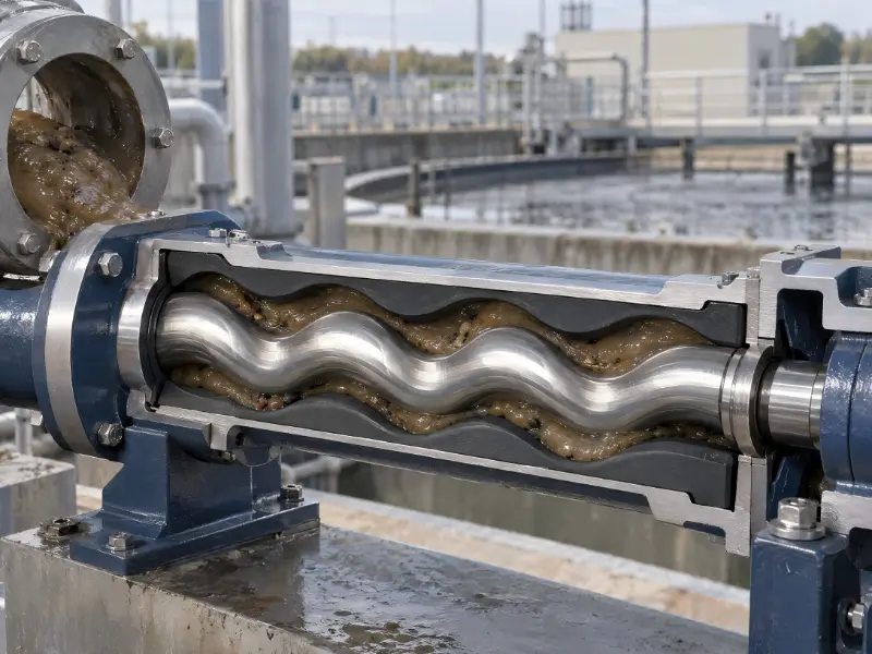
The G‑type single screw pump is an internal‑meshing rotary positive‑displacement pump. Its main working components consist of an eccentric screw rotor and a fixed rubber‑lined stator. As the screw rotates inside the stator, the two mesh to form a series of sealed cavities, which continuously push the medium from the suction end to the discharge end. It delivers stable flow rate, strong self‑priming capacity, and can handle high‑viscosity media as well as media containing solid particles and fibres. It is widely used in wastewater treatment, chemical slurry processing, food sauce handling and other working conditions.


However, “being usable” does not equal “being correctly selected”. Liner detachment from the pump barrel, rubber chunking biting the rotor, frequent shaft seal leakage, motor overload tripping — the vast majority of on‑site problems stem from the failure to match medium properties with pump structural parameters during the selection phase. This document provides a set of practical selection procedures.


I. Operating Condition Parameters to Be Confirmed Prior to Selection


Selection should not start with model lookup but with defining operating conditions. If any of the following parameters is missing, the selection result will be unreliable:


  •  Medium properties: viscosity at operating temperature (not room‑temperature viscosity), density, corrosiveness (pH value and solvent type), solid‑phase content and maximum particle size, fibre length, susceptibility to shear‑induced denaturation
  •  Process requirements: normal flow rate and maximum flow rate, required pressure, continuous or intermittent operation, whether flow rate needs adjustment during operation
  •  Installation conditions: suction lift (self‑priming condition or flooded suction condition), ambient temperature, explosion‑proof requirements, noise limit


Take the Teffiko TPG‑series G‑type single screw pump as an example. Its application boundaries are: medium viscosity 20,000‑200,000 MPa·s (model‑dependent), maximum passable particle size 16 mm, maximum fibre length 100 mm, general solid‑phase content up to 40 %, and over 60 % for powdery media. For conditions beyond this range (e.g. strong solvents, sustained high temperatures), separate confirmation of stator rubber and wetted‑part solutions is required.

g-type-pump-article-illustration

II. Core Performance Parameters and Correction Methods


Performance test reference conditions. The performance tables and characteristic curves of G‑type single screw pumps are measured with 20 °C clean water (viscosity 1 cSt) as the test medium. When actual medium viscosity differs, flow rate and shaft power will deviate from water‑based data: higher viscosity reduces internal leakage loss and slightly raises volumetric efficiency, yet significantly increases friction torque between rotor and stator, leading to a notable rise in shaft power. Selection must be corrected according to real‑world operating‑condition viscosity; water‑based data cannot be directly adopted.


Output pressure and stator stages. Output pressure is determined by the number of stator stages: 1‑stage stator for 0.6 MPa working pressure, 2‑stage for 1.2 MPa, and 4‑stage for 2.4 MPa. Determine target pressure by summing process‑required pressure and pipeline pressure loss, then back‑calculate the required stator stages. For highly abrasive media, reserve adequate pressure margin to prevent accelerated stator wear from long‑term full‑load operation.


Speed characteristics. The G‑type single screw pump is a low‑speed pump. Rotational speed is selected according to medium abrasiveness and viscosity: higher viscosity and higher particle content call for lower rotational speed to mitigate stator wear, extend service life and ensure stable delivery. Industry practice specifies speed ranges by medium type — low speed for abrasive slurries, relatively higher speed for clean high‑viscosity media.


Safety‑valve configuration. Being a positive‑displacement pump, the G‑type single screw pump will experience continuous pressure build‑up if the discharge‑line valve is mistakenly closed. Exceeding component limits will cause liner detachment or even pump‑body rupture. A bypass‑type safety valve (or rupture disc) must be specified during selection, with its relief port routed back to the suction side. This is fundamentally different from centrifugal pumps, which can run briefly with closed discharge valves, and constitutes an indispensable item on the selection checklist.


III. Model Matching: Performance‑Parameter Comparison Table

Model Flow rate m³/h (8‑pole 720 r/min) Motor power kW (720 r/min) Flow rate m³/h (6‑pole 960 r/min) Motor power kW (960 r/min) Inlet × Outlet (mm) Reference Application
TPG10‑2‑V 0.08 0.55 0.1 0.55 25×25 PAM dosing
TPG13‑2‑V 0.3 0.75 0.4 1.1 25×25 PAM dosing
TPG15‑2‑V 0.45 1.1 0.6 1.1 25×25 PAM dosing
TPG20‑2‑V 0.6 1.1 0.8 1.5 25×25 PAM dosing
TPG25‑2‑V 1.5 1.5 2 2.2 32×25 Sludge transfer
TPG30‑2‑V 4 2.2 5 3 50×40 Sludge transfer
TPG35‑2‑V 6 3 8 4 65×50 Sludge transfer
TPG40‑2‑V 9 4 12 5.5 80×65 Sludge transfer
TPG50‑2‑V 15 7.5 20 7.5 100×80 Sludge transfer
TPG60‑2‑V 25 11 30 15 125×100 Sludge transfer
TPG70‑2‑V 40 18.5 — — 150×125 Sludge transfer


All models in the table adopt a 2‑stage stator configuration (“‑2‑” in model designation) with a rated pressure of 1.2 MPa. Flow‑rate and motor‑power values represent rated‑condition data. TPG10‑TPG20 are mostly used for low‑flow‑rate applications such as PAM (flocculant) dosing; TPG25 and above are intended for sludge and slurry transfer. Data source: Teffiko official website TPG product‑page performance‑parameter tables; refer to the latest manual in case of product‑document updates.


Recommended selection sequence: first short‑list candidate models by flow rate, then sequentially verify three points: whether the required pressure exceeds the capacity of a single‑stage stator for the selected model (increase stator stages if exceeded); whether medium viscosity and solid‑phase content fall within application boundaries; whether motor power satisfies viscosity‑corrected shaft‑power requirements.


IV. Stator Rubber Material Selection

The stator is a wearing part of single screw pumps, with a typical service life of 3‑6 months, and shorter service life for highly abrasive media. Improper rubber selection commonly causes stator detachment from the steel tube or rubber chunking, which in turn damages the rotor. Material should be matched to medium chemical properties instead of chosen based solely on experience.


Medium Type Recommended Stator Material Remarks
Clean water, sewage, sludge Natural Rubber (NR) Good wear resistance and elasticity; not resistant to oil and organic solvents
Oil‑bearing, hydrocarbon‑containing media Nitrile Butadiene Rubber (NBR) Oil‑resistant; resistant to alkali and mild weak acids
Weak‑acid, weak‑alkali and moderately corrosive media Neoprene Rubber (CR) Balances corrosion resistance and wear resistance
Strong acids and strong alkalis Ethylene‑Propylene‑Diene Monomer (EPDM) Acid‑alkali‑resistant and ageing‑resistant; not oil‑resistant
Organic‑solvent‑containing, high‑temperature oily media Fluoroelastomer (FKM) Solvent‑ and high‑temperature‑resistant; highest cost


V. Wetted‑Part Components, Shaft Seals and Drive Modes


Wetted‑part material combinations. Select cast‑iron or stainless‑steel (304/316L) combinations according to medium corrosiveness. Upgrade wetted‑part material grades for corrosive media to avoid the unfavourable scenario where the pump body corrodes before the rotor fails.


Shaft‑seal solutions. Mechanical seals and packing seals are two conventional interchangeable structures for easy maintenance and replacement. Mechanical seals are preferred for clean, low‑abrasion media (low leakage, long maintenance intervals); packing seals are widely used for particle‑laden abrasive media (low cost, particle‑tolerant, permits minor leakage). Make the choice according to operating conditions.


Drive modes. As a low‑speed pump, the G‑type single screw pump can adopt low‑speed motor direct‑drive (6‑pole / 8‑pole), gear‑reduction motor or variable‑speed motor. For in‑service flow‑rate adjustment, variable‑frequency or variable‑speed drive is preferred for smooth speed‑based regulation rather than throttling via outlet valves.


VI. Common Selection Pitfalls


1. Direct adoption of clean‑water performance tables: no correction for high‑viscosity conditions, resulting in theoretically sufficient flow rate yet actual motor overload.

2. Omission of safety‑valve installation: pressure rise upon valve closure for positive‑displacement pumps constitutes one major cause of liner detachment and pump‑body damage.

3. Stator‑stage sizing purely by pressure without abrasiveness consideration: blindly increasing stage count and rotational speed for abrasive media reduces stator service life down to weeks.

4. Empirically chosen stator materials: natural rubber used for oil‑bearing media, leading to swelling and chunking within a short period.

5. Neglect of suction lift: strong self‑priming capacity does not mean unlimited suction capability; installation height must still be calculated per product specifications.


VII. FAQ


What maximum‑viscosity media can the G‑type single screw pump handle?

The Teffiko TPG series covers viscosities from 20,000 to 200,000 MPa·s (model‑dependent). Conditions above this range require separate assessment.


What maximum‑size solid particles can pass through?

Maximum passable particle size 16 mm, maximum fibre length 100 mm; general solid‑phase content up to 40 %, and over 60 % for powdery media.


How frequently do stators require replacement?

Typically every 3‑6 months; shorter intervals for highly abrasive media. Prepare spare parts according to operating hours.


How is flow rate adjusted?

Changing rotational speed (via variable‑frequency or variable‑speed motor) delivers the smoothest adjustment. Bypass regulation is also feasible but introduces extra power loss from recirculation.


Is a safety valve mandatory?

Yes. Pressure will keep rising when discharge is blocked, so a bypass safety valve is standard equipment.


VIII. Summary


The core of G‑type single‑screw‑pump selection is to derive structural parameters from medium characteristics: viscosity determines rotational‑speed and power corrections; pressure determines stator stages; chemical properties dictate rubber and wetted‑part materials; abrasiveness governs shaft‑seal type. Completing these steps helps avoid most on‑site failures.


If you are selecting equipment for specific operating conditions, please contact Teffiko: we provide full‑range TPG‑series datasheets and one‑on‑one selection support. Visit our official website (https://www.teffiko.com) or send e‑mail to sales@teffiko.com.


Further Reading:


Related News
Leave me a message
  • BACK TO ATHENA GROUP
  • X
    We use cookies to offer you a better browsing experience, analyze site traffic and personalize content. By using this site, you agree to our use of cookies. Privacy Policy
    RejectAccept