After years of working in the industrial sector, I can say with certainty that progressive cavity pumps (also known as rotor-stator pumps, eccentric screw pumps) are absolute "staples" for fluid transfer. As positive displacement pumps, they are designed specifically to handle viscous fluids, corrosive substances, and media containing solid particles—they are indispensable in oil extraction, chemical plants, wastewater treatment facilities, and food production lines.
In my opinion, their excellent performance stems from the tight collaboration between the rotor and stator. To truly understand the working principle, performance, and long-term stable operation of progressive cavity pumps, you must thoroughly grasp these two core components. This is not just theoretical knowledge; it is hard-earned experience I have accumulated over the years.
In my eyes, the "lifeline" of every progressive cavity pump lies in the combination of the rotor and stator—the more precise their fit, the higher the pump’s efficiency.
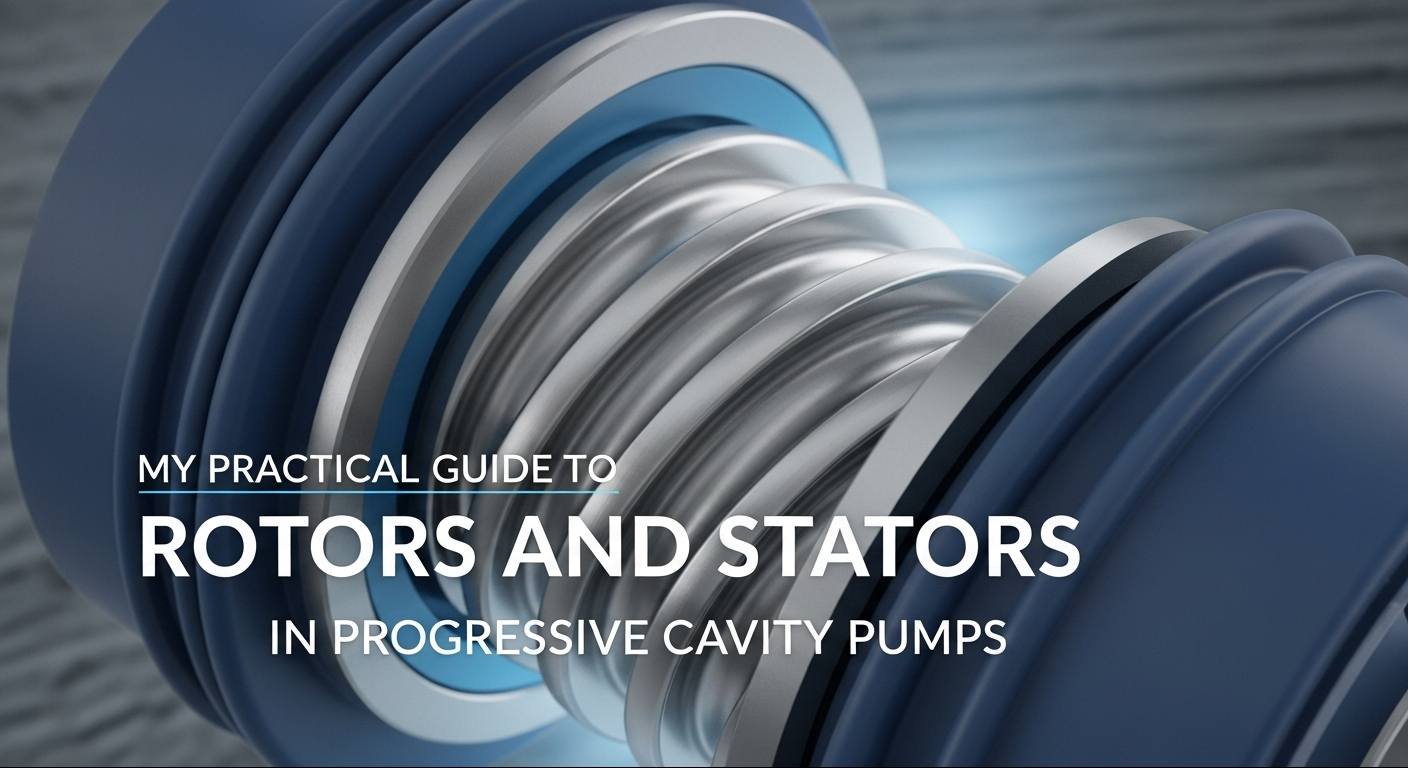
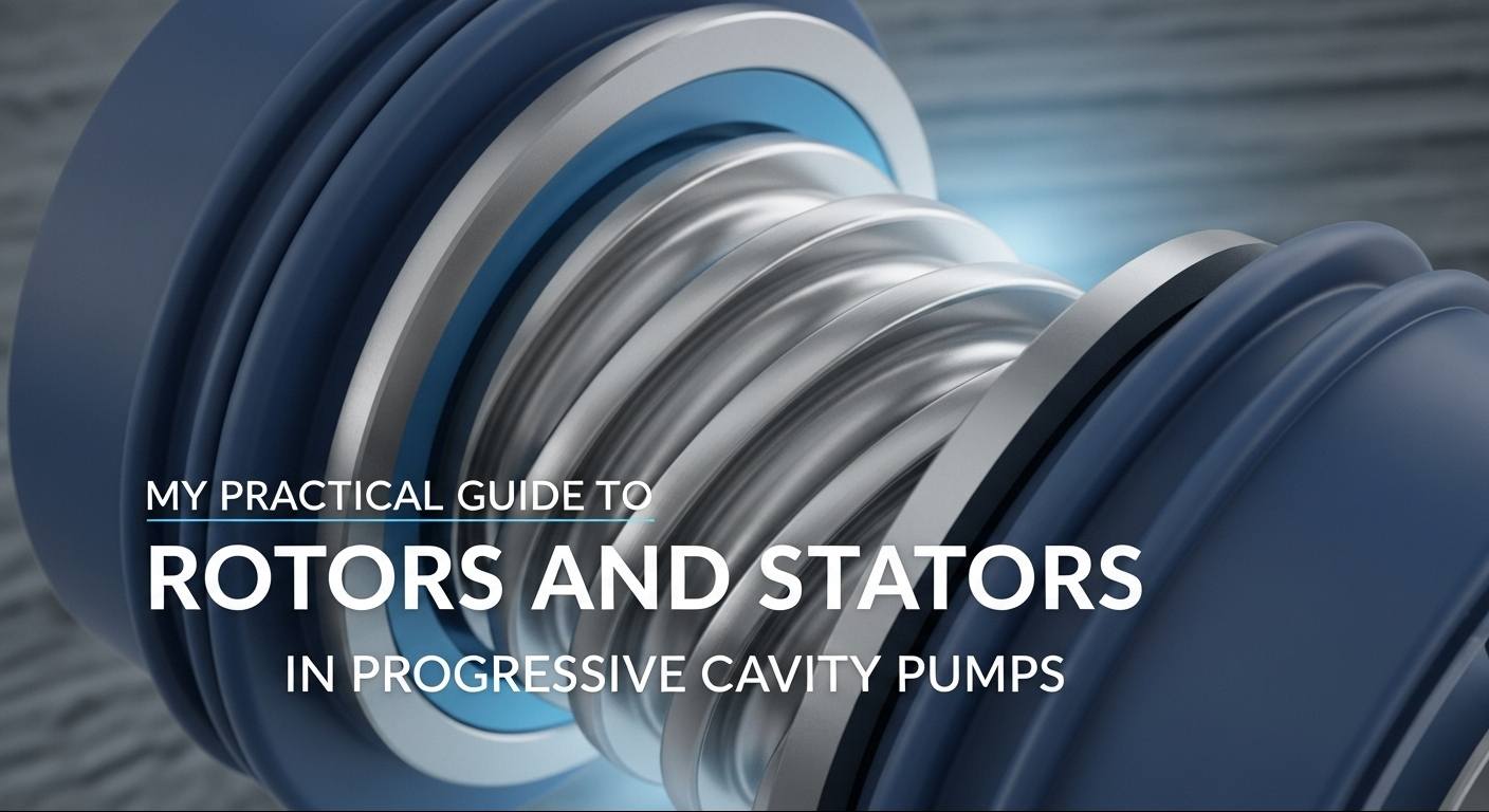
The rotor is a helically shaped metal shaft, usually made of high-strength stainless steel, alloy tool steel, or even titanium. As the active component installed inside the pump housing, it not only drives fluid flow when rotating but also generates the compression force required for transfer. I have seen many rotors undergo chrome plating or other surface hardening treatments, and frankly, this significantly enhances their wear resistance. Skipping this step will result in an annoyingly fast wear rate of the rotor.
The stator, on the other hand, is a metal tube with a molded inner cavity, lined with elastic materials such as nitrile rubber (NBR), fluororubber (FKM), or EPDM. Its internal shape fits the rotor perfectly, and the rotor’s diameter is slightly larger than the stator’s inner diameter. This "interference fit" ensures the formed chambers are airtight; if the seal fails, the pump is essentially useless.
Whether it is a single-screw pump (single-threaded rotor paired with a double-threaded stator), a twin-screw pump (two counter-rotating and intermeshing screws), or a triple-screw pump (one driving screw with two driven screws), I learned the hard way that the fit precision between the rotor and stator directly determines whether the pump can operate reliably. Even a tiny deviation may lead to reduced flow, leakage, or complete shutdown.
I didn’t fully understand the working principle of progressive cavity pumps until I disassembled two old pumps—it’s actually very easy to comprehend.
When the rotor rotates eccentrically inside the stator, their intermeshing helical structures form a series of sealed cavities. As the rotor turns, these cavities move steadily toward the discharge end, essentially "carrying" the fluid forward. It’s like having an invisible conveyor belt inside the pump, specifically designed for fluid transfer.
At the suction port, the cavity volume expands, reducing internal pressure, and fluid is drawn from the reservoir by atmospheric pressure; as the rotor continues to rotate, the cavity filled with fluid is pushed to the discharge port, where the cavity volume contracts, squeezing the fluid to increase pressure, allowing the fluid to be discharged smoothly.
What I particularly like about this design is that it requires no inlet or pressure valves at all. This not only achieves stable, low-pulsation transfer—crucial for sensitive processes—but also gently handles those "delicate" shear-sensitive materials, such as biopharmaceutical raw materials that can fail if subjected to improper force. Here’s a practical tip for you: reversing the direction of the rotor can switch the direction of suction and discharge. This small operation has saved me the trouble of reconfiguring the entire equipment several times.
Over the years, I have seen progressive cavity pumps outperform other types of pumps in many scenarios, but they are not omnipotent. Let’s objectively discuss their pros and cons.
After years of selecting pumps, I found that the geometry of the rotor and stator is the key to adapting to working conditions.
Pump Type Classification (My Quick Matching Guide)
In addition to basic pump types, subtle adjustments to the geometry of the rotor and stator can bring significant changes:
Additionally, parameters such as helix angle, lead, and tooth profile cannot be ignored. From my experience: the larger the helix angle, the greater the flow rate but the lower the pressure; the smaller the helix angle, the higher the pressure but the lower the flow rate. This is a trade-off that depends on the priority of the working conditions. Need to transport a large amount of viscous fluid? Choose a large helix angle; need high-pressure long-distance transfer? Choose a small helix angle.
Selecting a pump (including matching rotor and stator) is crucial to matching the working conditions. This is experience I gained after falling into countless pitfalls:
The selection of stator material is also crucial: nitrile rubber (NBR) for oil-based media, EPDM for high-temperature environments, and fluororubber (FKM) for corrosive media. If transporting highly corrosive fluids such as strong acids or solvents, don’t hesitate to choose a Hastelloy rotor—though expensive, it is much more durable than ordinary metals, lasting several years longer.
Adequate maintenance is the key to a pump’s longevity. This is my daily maintenance routine:
After all these years, I deeply understand that the rotor and stator are the core of progressive cavity pumps—and Teffiko understands this better than most brands.
As a reliable provider of industrial products and engineering services, they focus solely on core pump components. If you are looking for a progressive cavity pump that won’t let you down, I sincerely recommend Teffiko. Click here to learn more about their progressive cavity pump series
-