News

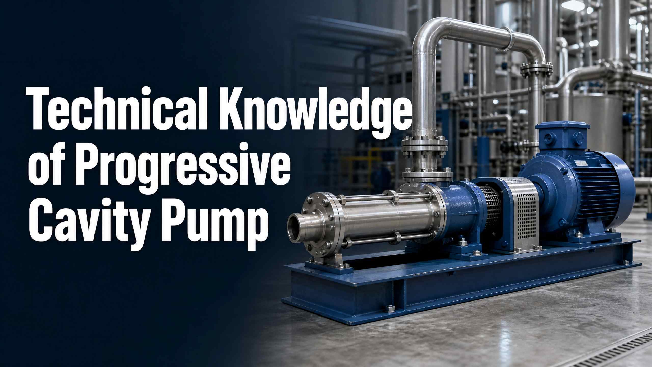
Technical Knowledge of Progressive Cavity Pump

2026-09-02 0 Leave me a message

I. What is a Progressive Cavity Pump


The Teffiko progressive cavity pump is a positive‑displacement conveying equipment. It consists of an eccentric helical rotor mated with a double‑helical surface bushing (stator) to form closed cavities for medium displacement. It features stable pulsation‑free flow, low shear force, strong self‑priming capacity and broad medium compatibility. It is especially suitable for conveying high‑viscosity media, media containing hard particles, fibrous materials and shear‑sensitive substances prone to tearing. Unlike centrifugal pumps, progressive cavity pumps do not rely on high‑speed impeller agitation. The medium undergoes no violent churning or vortexing, and its original properties can be fully preserved. It is widely applied in complex conveying scenarios such as sewage and sludge, industrial slurries, food pastes and viscous chemical liquids. Meanwhile, the pump boasts a compact structure with few components, enabling easy disassembly, assembly and maintenance, even for novice operators.

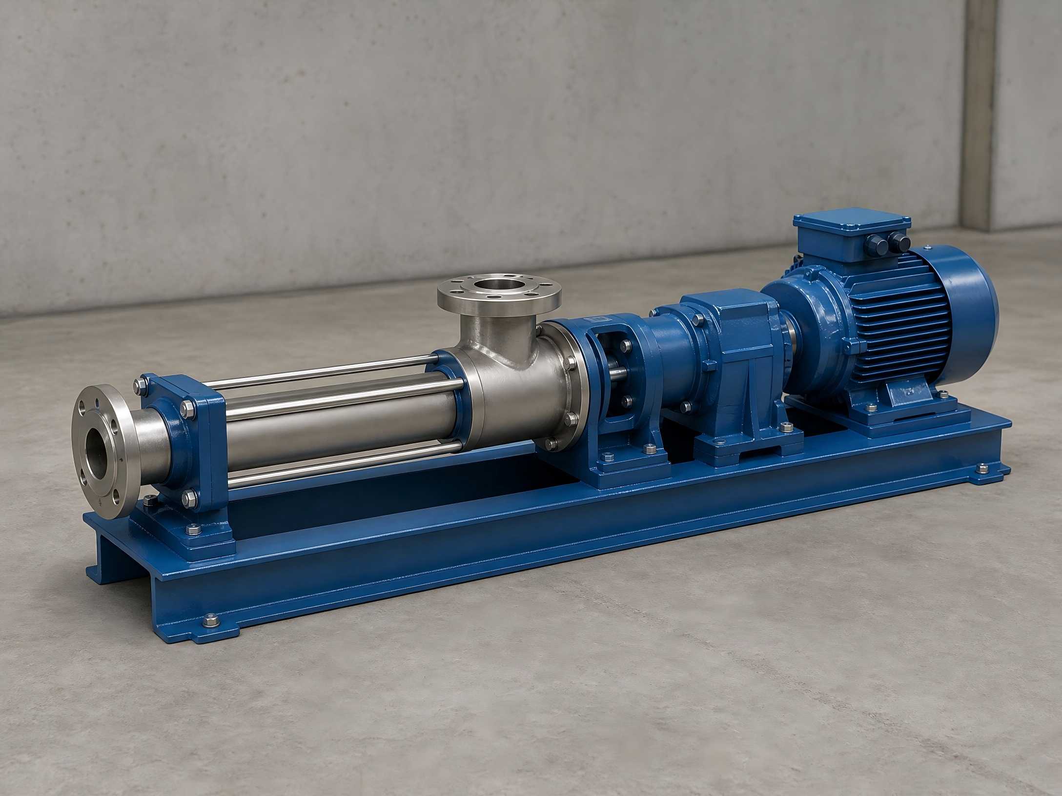
progressive cavity pump

II. Core Working Principle of Progressive Cavity Pump


The core operating structure of a progressive cavity pump comprises a single‑thread helical rotor paired with a double‑helical rubber stator. Their unique geometric configuration forms independent closed medium chambers. During operation, the motor drives the pump shaft, causing the rotor to rotate about its own axis while rolling along the inner surface of the stator, continuously generating successive sealed chambers. For each full rotation of the rotor, the medium advances by one pitch. With continuous rotor rotation, the medium is axially and evenly pushed from the suction end to the discharge end via helical propulsion. Throughout the conveying process, internal flow velocity remains low and chamber volume stays constant, free of vortices and agitation, delivering stable pressure and fundamentally preventing medium degradation and emulsification.


 Core Technical Operating Parameters and Characteristics


  •  Pressure and head: A single‑lead stator delivers an output pressure of 0.6 MPa, corresponding to a clear‑water head of 60 m; a double‑lead two‑stage pump achieves a pressure of 1.2 MPa, corresponding to a head of 120 m. Multi‑stage pressure specifications can be selected according to working conditions.
  •  Self‑priming performance: Standard self‑priming height reaches 6 m. Priming is not required in advance, offering excellent self‑priming capability.
  •  Medium temperature: Standard models are suitable for media below 80 °C. Custom special models can withstand high‑temperature operating conditions up to 150 °C.
  •  Flow characteristics: Flow rate has a strictly linear positive correlation with rotational speed. Flow remains stable at constant rotational speed.


Important Prohibition: Progressive cavity pumps are strictly forbidden to run dry. Under dry‑running conditions, the rotor and stator lack lubrication and cooling from process medium. Friction rapidly generates high temperature, which readily scorches, cracks and ages the rubber stator. This constitutes the primary cause of equipment damage and shortened service life.


III. Core Structural Components


1. Rotor


The rotor is a metallic eccentric helical shaft and the core power‑generating moving component of the equipment. Commonly used industry materials include 304 stainless steel, 316 stainless steel, hard‑chrome plating and wear‑resistant alloys to suit various corrosive and abrasive working conditions. The machining precision and surface wear resistance of the rotor directly determine pump flow stability, conveying accuracy and overall service life. Wear‑reinforced rotors are preferred for long‑term conveyance of abrasive media such as mud and hard‑particle‑laden fluids.


2. Stator


The stator is a rubber bushing with an internal double‑helical profile. It represents the most critical and most consumable key component of the progressive cavity pump, and also the core part enabling the pump to handle complex media. Leveraging the properties of various elastic rubber materials, progressive cavity pumps possess conveying capabilities unavailable to conventional pump types, reliably transporting high‑viscosity fluids, fluids with suspended hard particles and fibrous‑laden complex media. Different rubber materials are matched to defined working conditions:


  •  NBR (Nitrile Butadiene Rubber): General‑purpose grade with outstanding oil resistance. Suitable for sewage, sludge, common oily fluids and conventional media.
  •  EPDM (Ethylene Propylene Diene Monomer Rubber): Acid‑alkali resistant, heat‑resistant and anti‑aging. Applied for hot‑water and weakly‑corrosive industrial medium conveyance.
  •  FKM (Fluoroelastomer): High‑performance corrosion‑resistant material featuring heat resistance, strong acid‑alkali resistance and chemical corrosion resistance. Used for various special chemical medium working conditions.


3. Universal Joint Drive Assembly


It mainly transmits eccentric torque and connects the front drive shaft to the rear rotor, serving as the core hub for power transmission. During equipment operation, this assembly is continuously subjected to alternating loads. Wear accelerates when conveying media containing solid particles and impurities, making it a key focus for routine equipment inspection and maintenance.


4. Pump Casing, Inlet / Outlet and Drive Assembly


The pump casing provides medium containment and sealing protection. Inlet and outlet flanges comply with standard pipe installation requirements. The drive assembly consists of a motor and a reducer, supporting fixed‑speed operation, stepless speed regulation and multi‑speed variation. Rotational speed can be flexibly adjusted to precisely control conveying flow and satisfy diverse production requirements.

industrial single screw pump

IV. Core Advantages and Model Features of Progressive Cavity Pump


  •  Stable and precise conveyance: Flow and pressure are free of pulse fluctuations with constant chamber volume. Combined with speed‑governing systems, flow accuracy can reach ±1 %. It can function as a precision metering pump for high‑accuracy scenarios including laboratory applications, chemical dosing and industrial batching.
  •  Exceptional medium compatibility: Handles clean water, high‑viscosity slurries, pasty substances, particle‑bearing and fibrous‑containing media, breaking through the conveyance limitations of ordinary pump types.
  •  Low‑shear conveyance: No vortices or violent agitation during operation. Materials will not be torn or emulsified, making it ideal for food, biological and fine‑chemical industries demanding medium integrity.
  •  Flexible model configuration: Identical pump bodies can be custom‑designed into vertical, inclined or mobile trolley‑mounted configurations to accommodate diverse site layouts and working‑condition installation requirements.
  •  Convenient operation and maintenance: Simple overall structure with few components. Disassembly, inspection and maintenance are easy with low skill barriers.
  •  Excellent self‑priming performance: Standard self‑priming height of 6 m. Auxiliary priming equipment is unnecessary for convenient startup.


V. Core Hydraulic Anti‑Reverse‑Rotation Technology for Progressive Cavity Pumps


Hydraulic anti‑reverse‑rotation technology is a specialized core technology addressing safety hazards caused by high‑speed rod string reverse rotation upon pump shutdown or pump seizure for progressive cavity pumps. During shutdown or pump seizure of conventional progressive cavity pumps, torsional potential energy stored within the rod string and pressure differential between tubing and casing release rapidly, triggering high‑speed reverse rotation of the rod string. Enormous instantaneous torque is generated, which may easily bend or fracture polished rods, cause rod‑string disconnection, lead to high‑speed fragmentation and ejection of belt pulleys, damage surface equipment and even result in personal safety accidents.


This technology relies on an independent hydraulic anti‑reverse‑rotation device for safe torque release without manual intervention. When the main shaft develops a reverse‑rotation tendency after shutdown, hydraulic brake caliper pistons inside the device extend automatically, pushing friction pads to clamp the brake disc, rapidly reducing system pressure and restraining reverse‑rotation speed. After brake caliper pressure subsides, the main shaft rotates slightly backward, the gear pump restarts operation and the brake caliper clamps the brake disc again. Through a flexible “clamp‑release‑cyclic braking” mode, reverse‑rotation torque of the main shaft is gradually reduced to zero to completely eliminate safety risks.


Core technical advantages: Built‑in one‑way constant‑pressure unloading mechanism, large braking torque, smooth braking and favorable heat‑dissipation performance for automatic residual‑torque release. The device adopts an independent modular structure. No modification to the main pump body is required; retrofitting can be performed directly on existing drive equipment, featuring simple operation, low reconstruction cost and superior compatibility.


 VI. Routine Operation and Maintenance Guidelines


1. No dry startup: Fill the pump chamber with medium before startup to achieve lubrication and cooling, and prevent thermal burnout failure of the stator.

2. Reasonable rotational‑speed control: Higher rotational speed yields greater flow rate yet accelerates wear of rotors, stators and universal joints. For abrasive‑medium conveyance, operate at a reasonable low‑speed range to extend equipment service life.

3. Periodic special‑purpose inspection: Focus on monitoring operating conditions of universal joint drive assemblies, mechanical seals and braking devices. Timely identify hazards such as wear, leakage and braking failure.

4. Shutdown maintenance and cleaning: For long‑term equipment shutdown, thoroughly flush the interior of the pump chamber to prevent medium solidification and caking that would block chambers or corrode components.

5. Timely replacement of consumable parts: Obvious drop‑offs in flow rate and pressure are mostly caused by wear and aging of rotors and stators. Replace components promptly to guarantee equipment operating accuracy.


Related News
Leave me a message
  • BACK TO ATHENA GROUP
  • X
    We use cookies to offer you a better browsing experience, analyze site traffic and personalize content. By using this site, you agree to our use of cookies.Privacy Policy